Working from home, from my new “Home Office” (previously Guest Room) has worked fairly well, but the one area it has not worked well in is taking Video Conference Calls. While it usually works, I frequently will get part of the video call which is jittery video wise, or gets the audio dropped briefly. While this could just be seen as annoying, it is frequently a barrier to communicating remotely, and can be extremely frustrating.
I have a good internet connection, and a fairly decent wireless network, but it can not be avoided that wireless packets get dropped from time to time, and the performance is not fully reliable. This is especially true when others are gaming on the network or streaming videos. The solution is pretty clear, I need a wired connection to my office, so I can hard-wire my laptop into my home network.
The Problem
So, the solution is clear, a wired Ethernet connection to the room. The problem is that it is not easy to get to, for the following reasons:
The office is on the opposite side of the house from where the Internet connection comes into the house, about 50 ft away.
The room under the office is the garage, but it is fully finished, with no exposed studs, limiting access to above.
The office is also on the 1st floor, on a 2 story house, so there is no way to come at it from above either.
The wall I want to add it to, is an exterior wall, which has insulation, and also makes it very difficult to drill from below even if the studs were exposed.
So, basically there is no easy way to install an Ethernet Jack.
My usual go-to move, would be to identify the wall from below in basement, drill up through the floor in the wall cavity (separating the 2 rooms), and put a box in the wall attached to the wire fed from below. That wire could also easily be routed in the basement, because with nothing finished, it is fairly clean to route it along the joists.
Step By Step
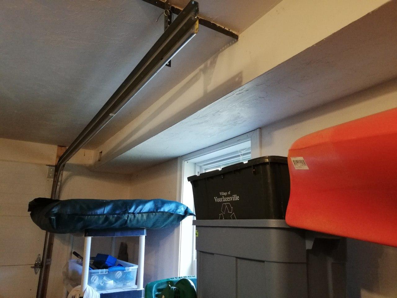
To be honest, I had tried to find a solution for this before (for a printer), but it is now becoming more important that I do find a solution. After, further inspection, there is a bulkhead which may be a possible solution.
Bulkhead in Garage
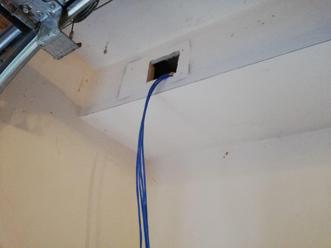
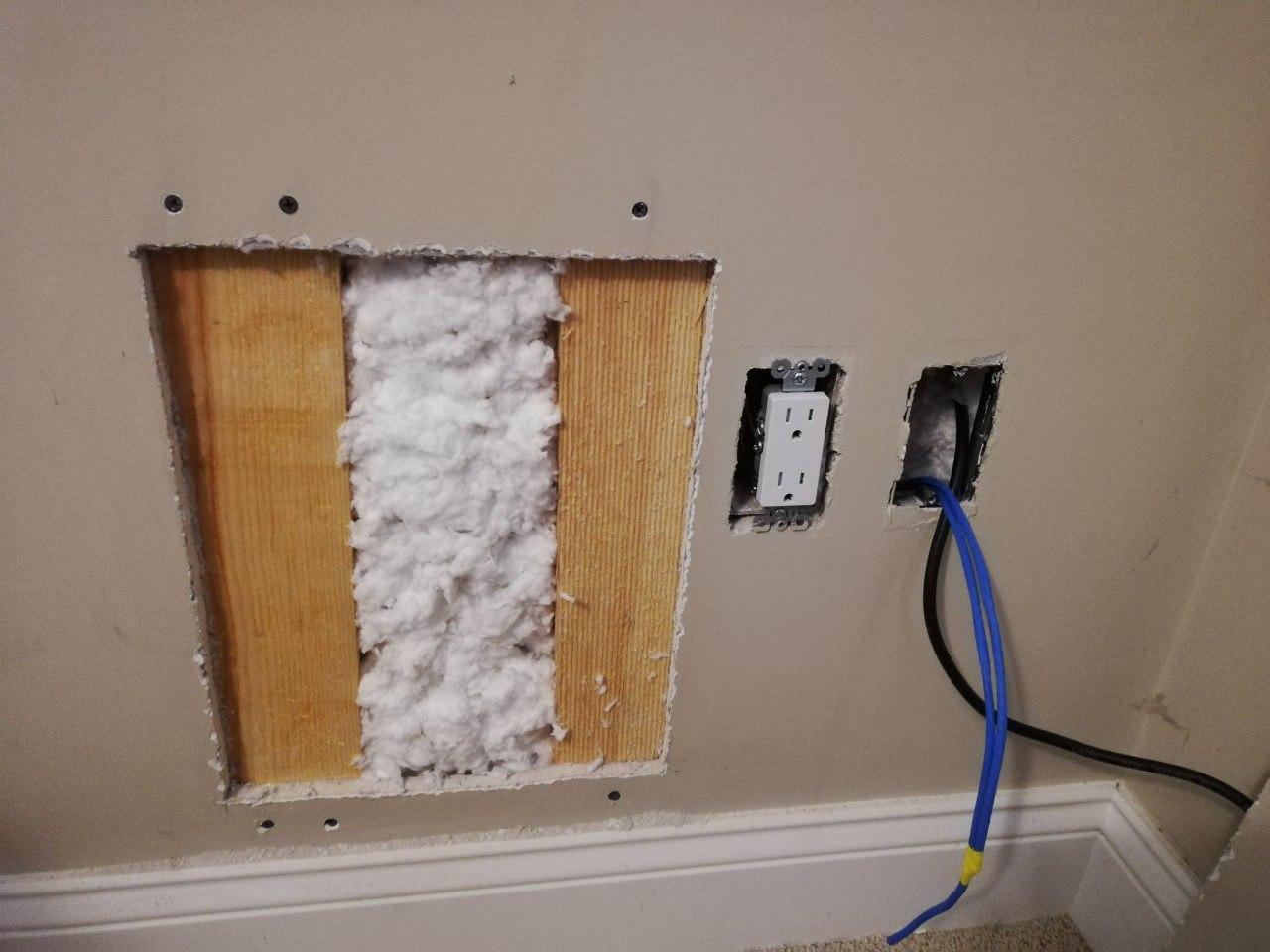
The first step, can I get a connection from the office, down into this bulkhead? I thought, if I cleared a big enough space in the wall, that it would be possible to get a drill in there, and drill a hole diagonally from the cavity in the wall, towards the garage (away from the exterior). After clearing a hole in the sheetrock, and trying it out, it worked.
New hole in wall, along with existing outlet and coax connection.
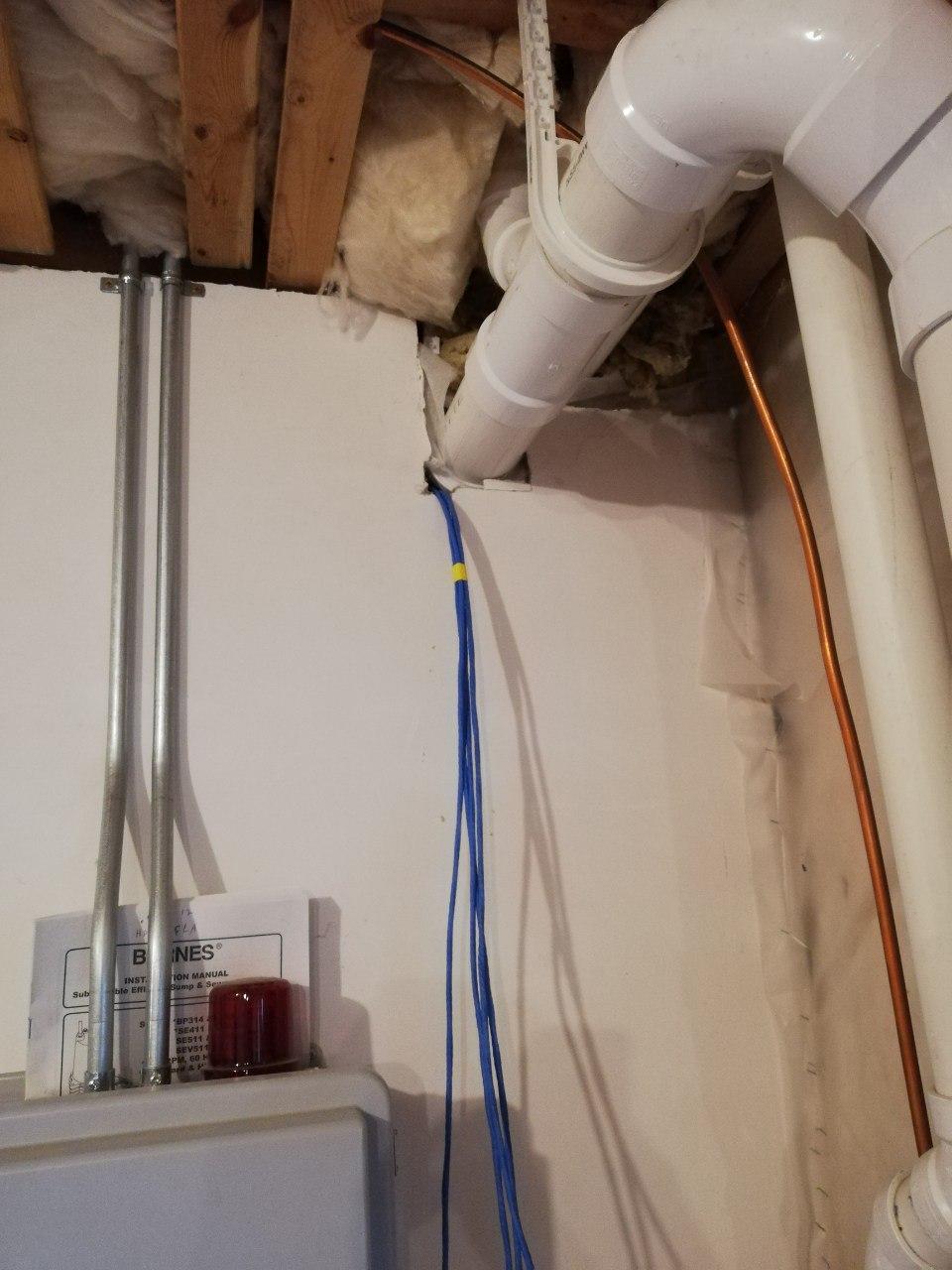
Now that we can get a wire downstairs, the next step is to run it along the bulkhead. This took a while, and a lot of diligence, but with tons of work, I was able to feed a more solid guide wire down the bulkhead (this was assisted with a hole half-way down the length), and I was eventually able to pull the Ethernet wire along it.
Ethernet wire fed through bulkhead. Note the 4 wires (not one), 1 for computer, 1 for printer, and 2 for security cameras that will be another job later down the road.
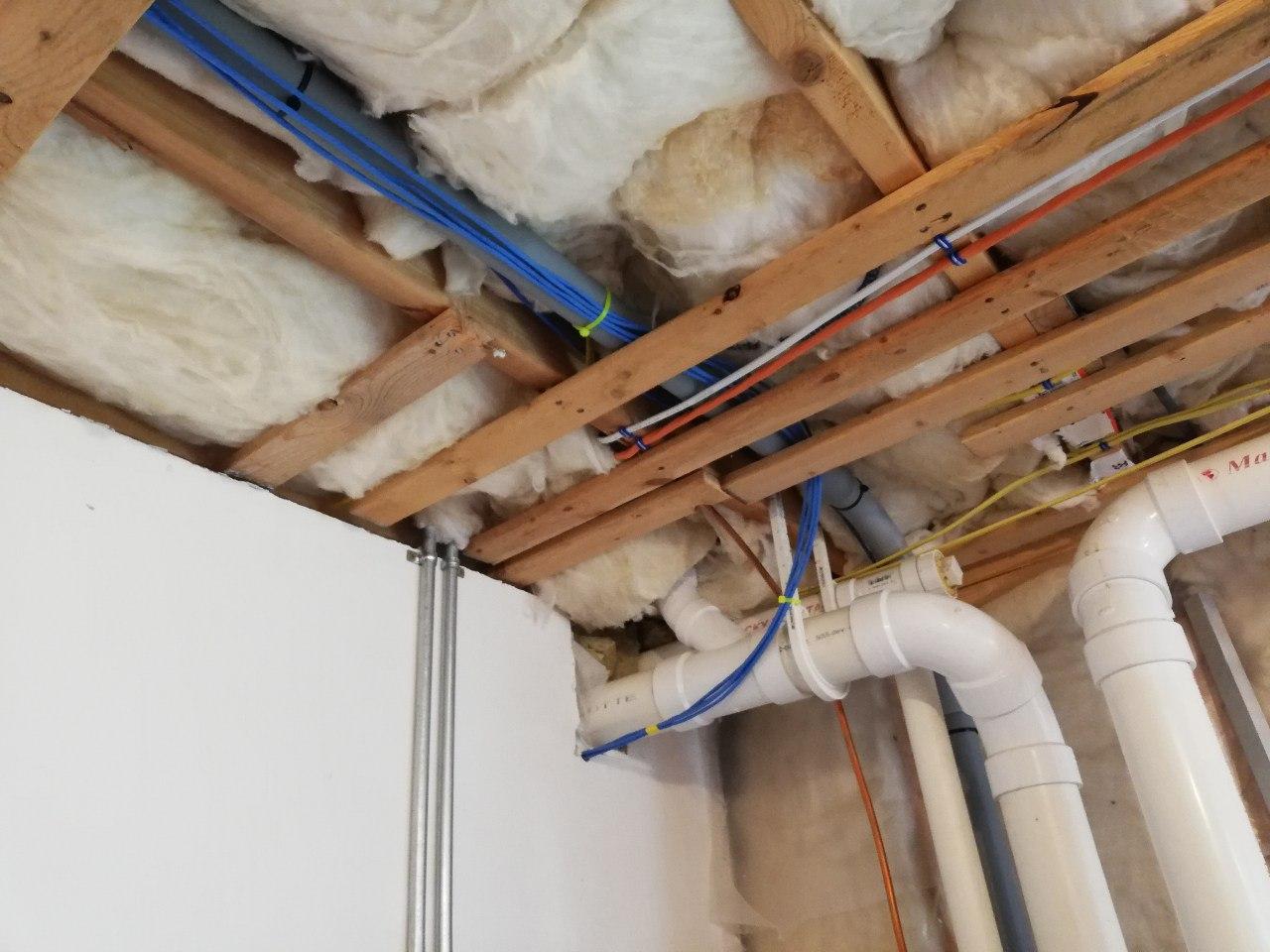
Ethernet wire from bulk head, running into the rest of the basement.
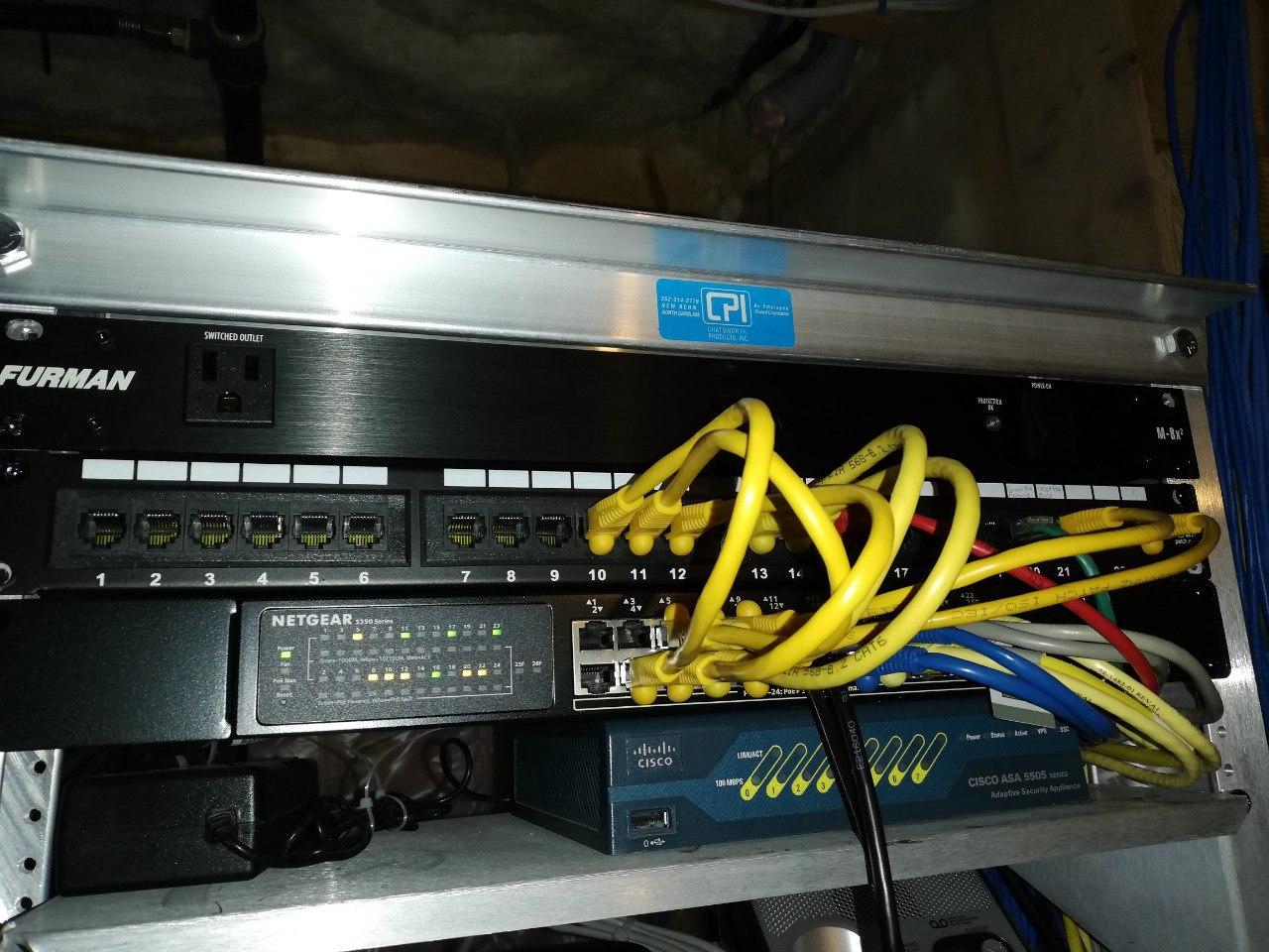
With those steps behind us, the rest are fairly straightforward. The first is to route the wires to the Home Internet connection, and to clean them up with zip-ties, and patch them into the existing network switch.
Zip-tied cables all cleaned up.
Patch panel connected with 4 new Ethernet wires into switch.
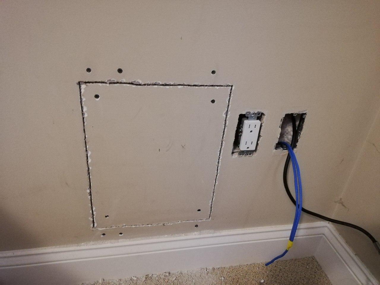
The last step was to close up the existing hole, and to install the new jacks.
Wall opening with furring strips added to support sheet-rock, and insulation put back into place.
Closed up wall, just waiting for mud to finish it off.
Finished
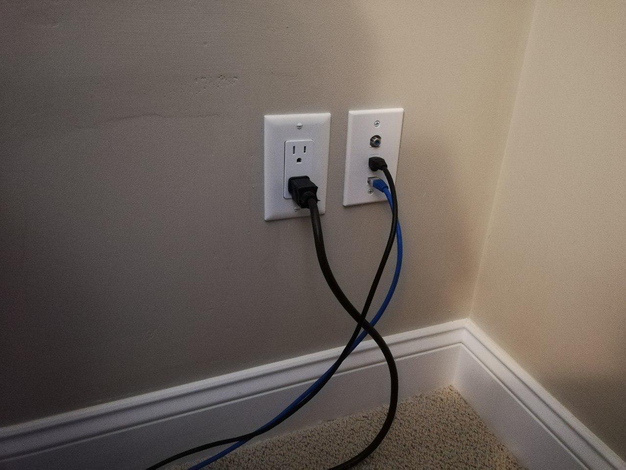
Finally, 2 new network jacks in my office. One for my laptop, and one for the printer that was already there (previously using Wi-Fi).
2 New Network Jacks with patched up wall. Success.
For the past 3 years our pool has been using one of the very common analog pool pump timers (eg. Intermatic T104R3 Time Switch) to turn the pump on day in and day out, but that all came to an end last week. One day I noticed that the pool was never turning off, and the time was not changing on it. Opportunity knocks!
Overview
Time to get rid of that old analog timer, and to replace it with a new digital device, one that can be controlled remotely and can be queried at any time.
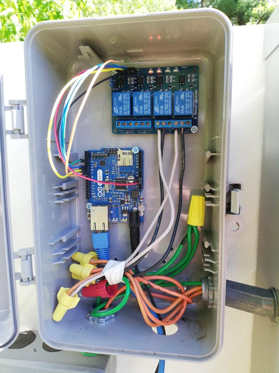
New Pool Controller: Arduino and Relay Module
Components
As sometime who tinkers from time to time, I just happened to have everything I needed on hand to make this a reality. The key were the following 2 components:
Arduino Ethernet – This became the new controller, and a lot more advanced then the old timer.
By putting these 2 together, we get exactly what we want. A remotely controllable switch to turn the pump on and off.
Install
The existing timer came in a nice waterproof case, so the first step was to remove that old broken timer from the existing case, of course remembering to shut of all associated power first.
Existing Analog Timer
With the timer removed, there was just enough room to install the Arduino and Relay Module. These were installed in such a way to make room for each other, and to also allow for upgrading of the firmware in the future (which ended up being needed immediately). After that was done:
The existing braided power lines were connected to the relays with some new solid core power wires using wire-nuts.
The Arduino was wired up to the relay module.
For simplicity reasons, power was delivered via an external power transforming and a nearby outlet.
Network was supplied via a short Ethernet cord, and a jack which was previously installed for a Network Access Point.
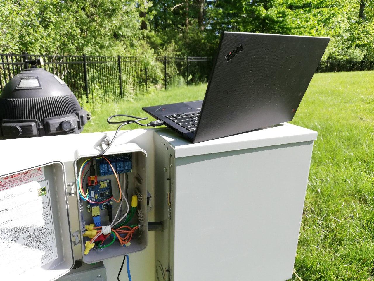
Arduino and Relay Module Installed
All the necessary components are now in place.
Software
This is one of the areas in which I really won. Years ago, I was working on putting together software for an Arduino based project on which I could control the lights near my pool. The concept was to expose an HTTP interface which would turn the lights on and off. It was a simple pivot, to change this to control the pool, and a couple more HTTP endpoints to accommodate that.
With the updated code, the Arduino starts up, grabs a Dhcp address on the network, and then exposes the following endpoints:
/ – Status page which reports the current state of the controller
/pump/off – Turns the pump off
/pump/on – Turns the pump on
/uptime – Returns uptime of the device (this was used mostly for debugging)
This code was all written in C++, and uploaded via a serial connection.
As you may have noticed, there is nothing turning the pool on or off at this point. That was achieved with a simple cron script on a local server that I use for many other things. This is what that looks like:
All in all, I am very pleased with how this came together. I would say that it came down to equal parts luck (having the right components on hand), and previous work (having most of the software complete). There was a little bit of debugging to resolve a couple small issues, but after that, new working pool pump controller. All in all, very satisfied.
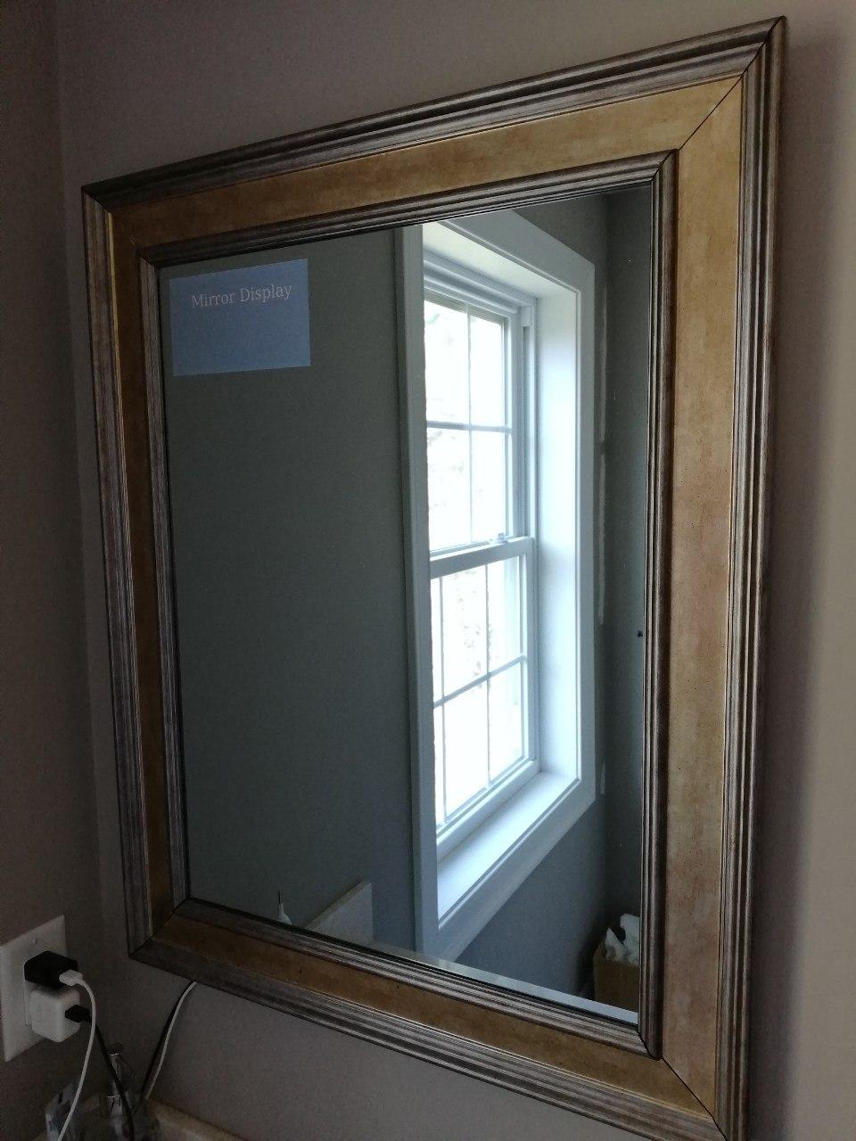
This project has been a long time in the making. A couple years ago, I initiated the process of creating a mirror display with an old mirror, a new two way mirror I acquired online, and a cheap tablet. Unfortunately an old android tablet wasn't great for this project, for multiple reasons. This article will concentrate on resurrecting that project, and specifically the hardware part of this project.
Overview
As seen and productized many places on the internet, this project is to build a mirror, which when activated shows a screen from behind it, and then when disabled disappears again completely. I have found this to be pretty cool since the first time I saw it, and this is the first time I have a real plan on building a decent solution. My intent here is to build a screen that can show me supplemental information in the morning while I am getting ready, such as the weather, my schedule for the day, or just a photo memory of the family.
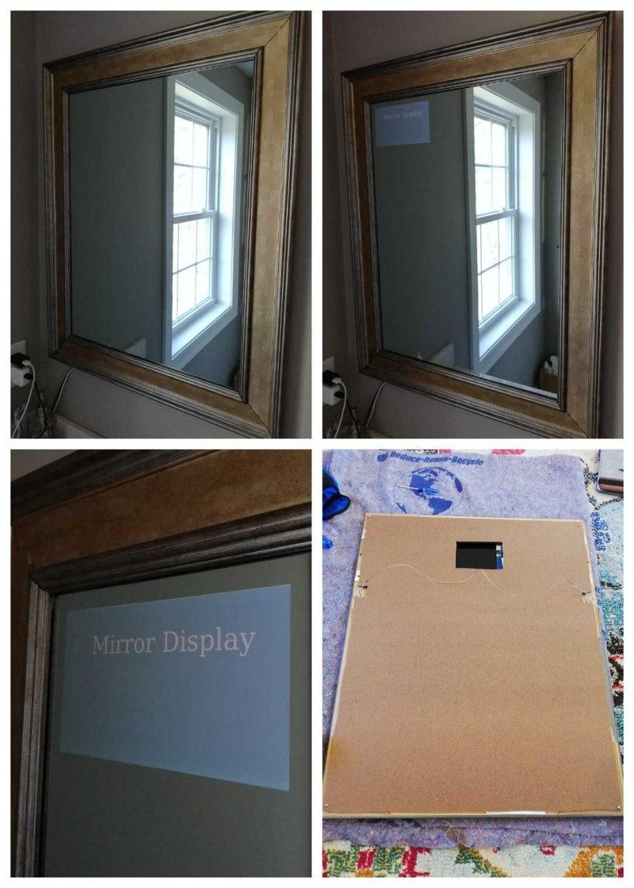
Finished Mirror hanging in Bathroom. Upper Left - Display Off, Upper right - Display On, Bottom Left - Zoom In on Display, Bottom Right - Back of Mirror when complete (without RaspberryPi attached)
Mirror
This was the easiest step. This mirror is one of two matching mirrors that I had in my bathroom previously. As mentioned, years ago, I replaced the mirror in it with a 2-way mirror, and put a tablet behind it. The first step here was to remove the old tablet, and to start getting it prepared.
Display
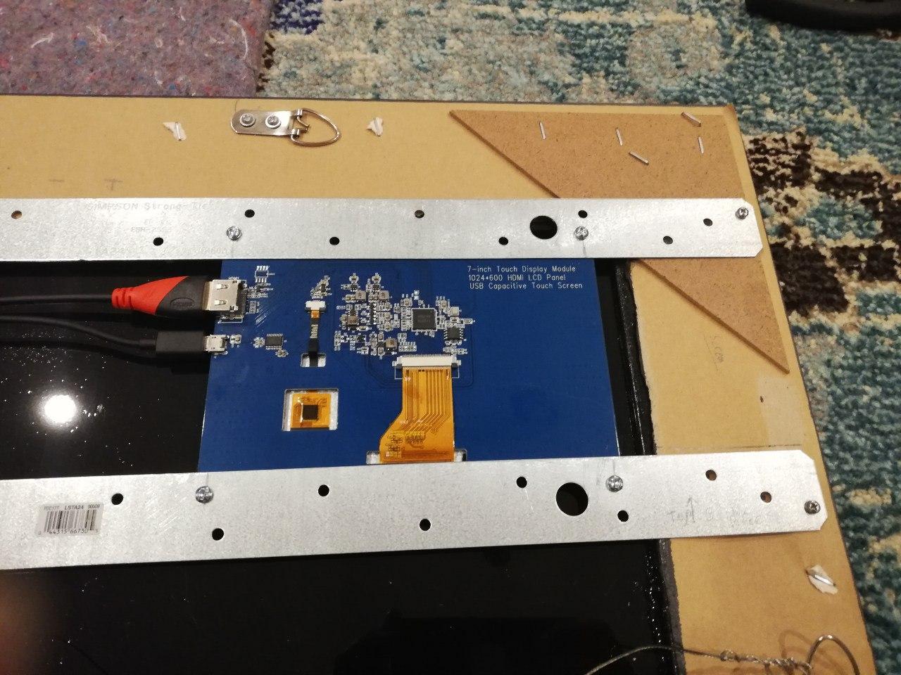
Recently I found an inexpensive Raspberry Pi screen with the SunFounder 7'' 1024×600 LCD Screen, that with a Raspberry Pi (Zero W) would make a great replacement for the old tablet. Full control of what is displayed, and full capability to automate and update device as needed.
Process
Preparation
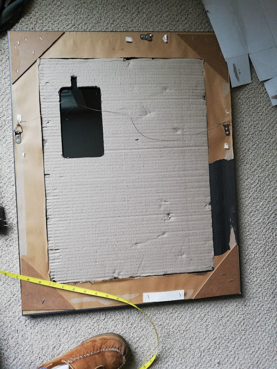
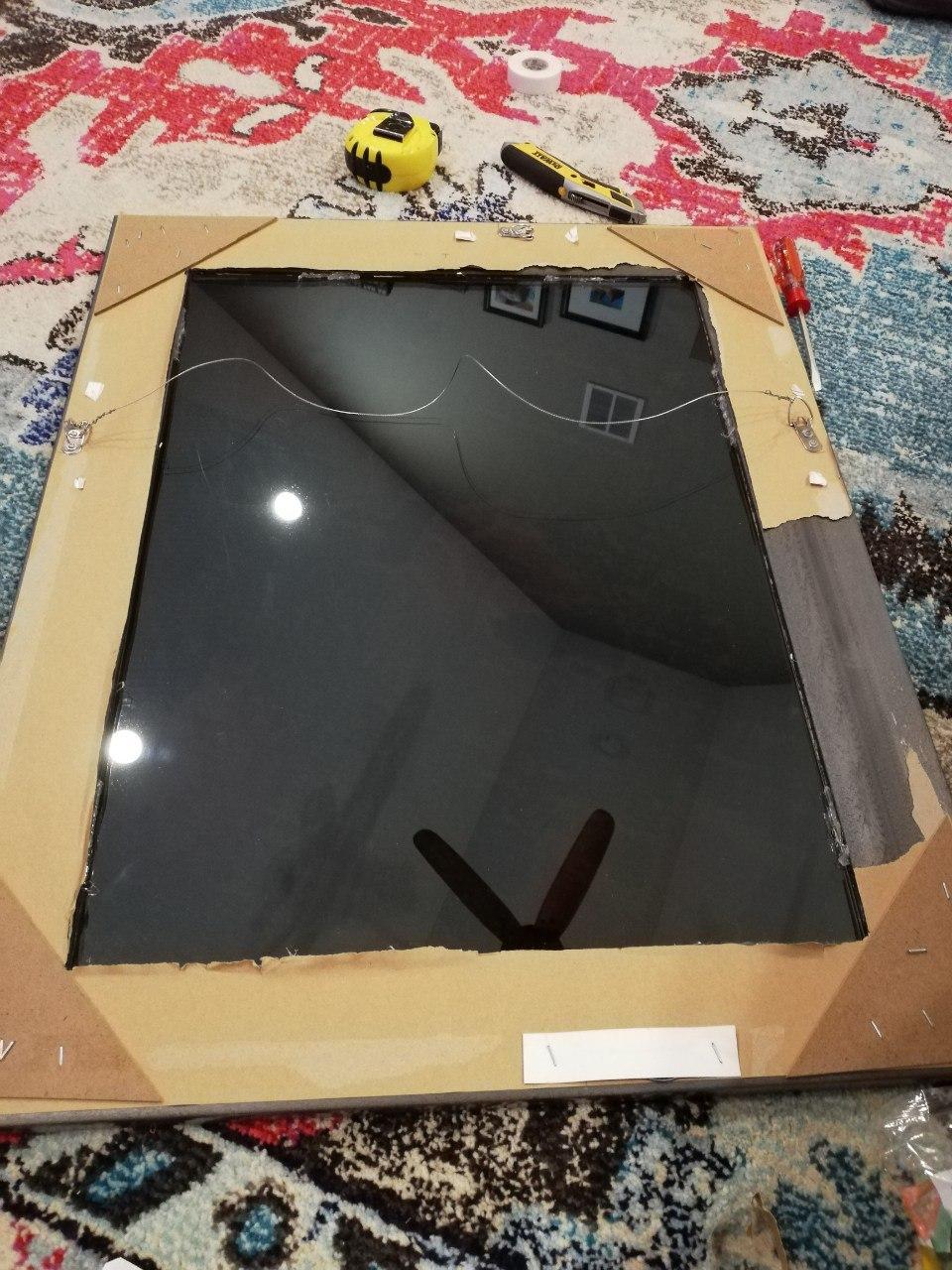
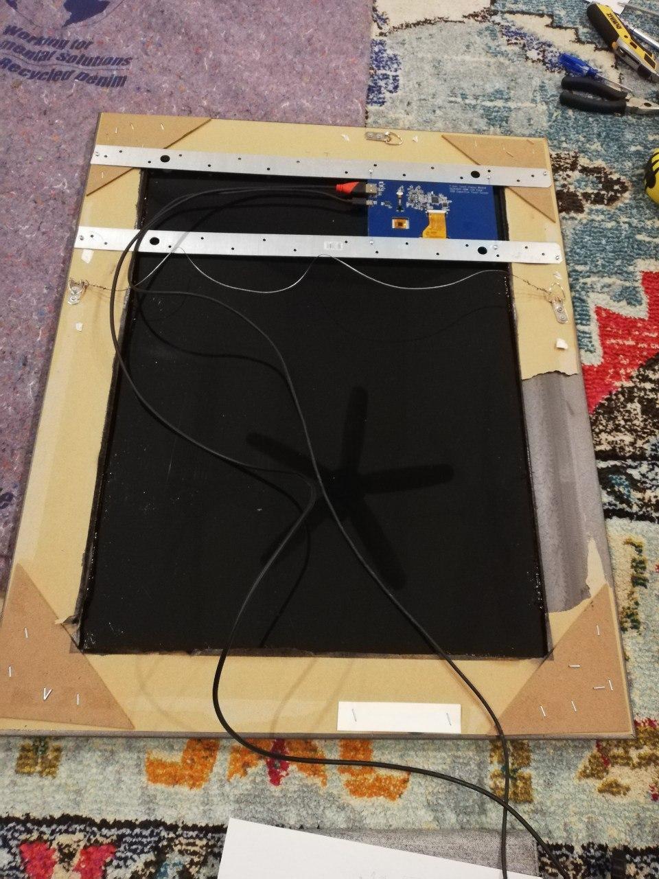
The first step here was to get the mirror ready for the project. This included taking down the mirror, removing the old back (which as you can see, was not a quality job before), and removing the tablet/cardboard behind the glass.
Glass Preparation
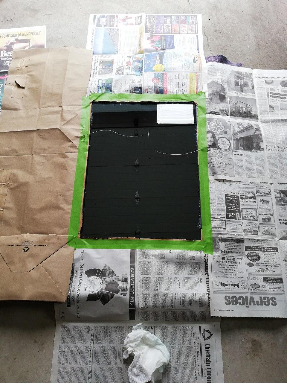
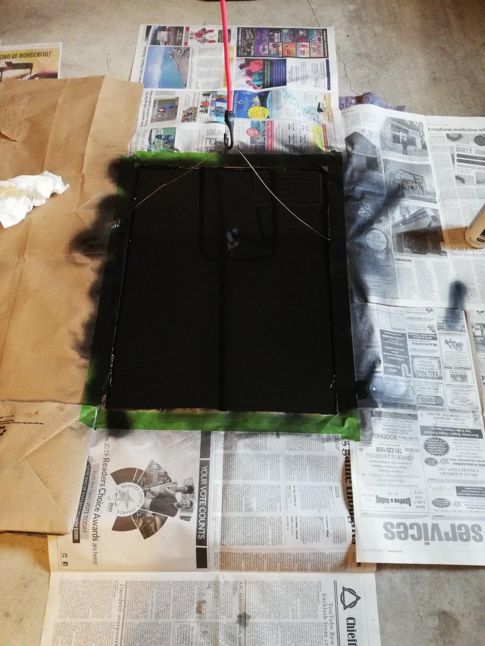
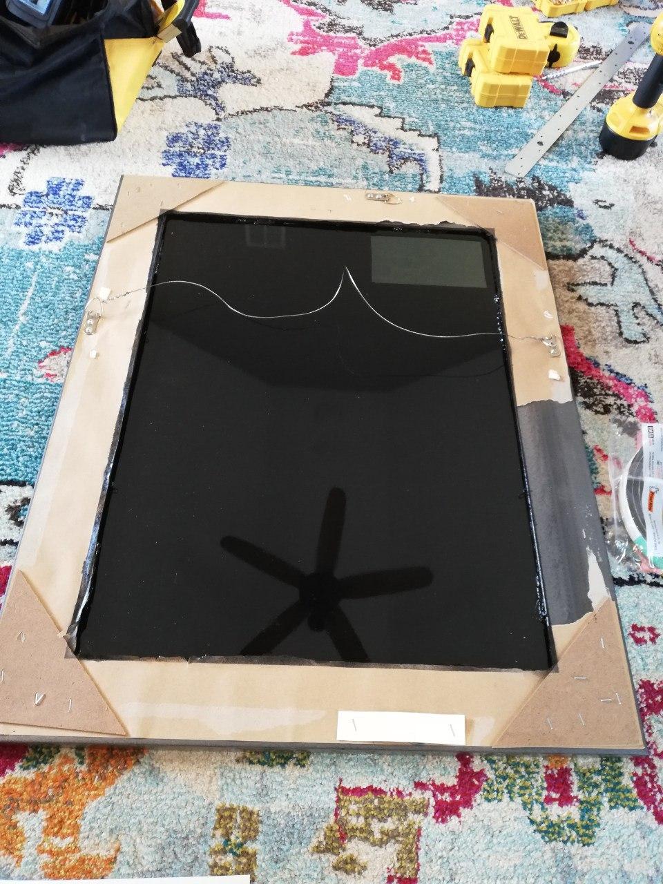
One of the problems I encountered before, was that with the light cardboard behind the glass, in some cases when the sun shined directly on the glass, it would reflect from the cardboard which would make the cardboard visible from in front of the mirror. To solve this problem, I decided to spray paint the back of the glass that would contain the screen and leave only the screen area exposed. To do this, I first taped off the area where the screen would go, spray painted the exposed areas black, and then removed the tape to expose the glass.
Screen Mounting
Now that the mirror is prepared, the next step was to test the display, and then mount it on the mirror. To test the screen, I attached it to a Raspberry Pi with software that I will discuss in a followup post. After testing was complete, I used a couple brackets purchased from Home Depot, to position the screen directly over the exposed mirror area. This was done while the screen was on to position in exactly the right spot.
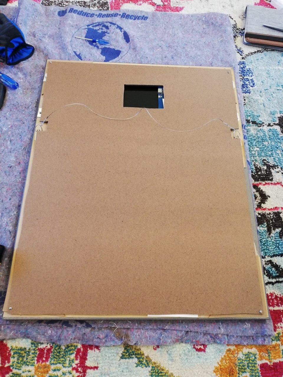
Finish
To finish off the mirror, the cardboard was added back to the mirror for a needed buffer, and a new piece of backing was mounted to the back of the mirror (with a space for the connectors of the display, and room for inserting the Raspberry Pi). From there, the Raspberry Pi was inserted, cables were connected, power was plugged in, and the device booted.
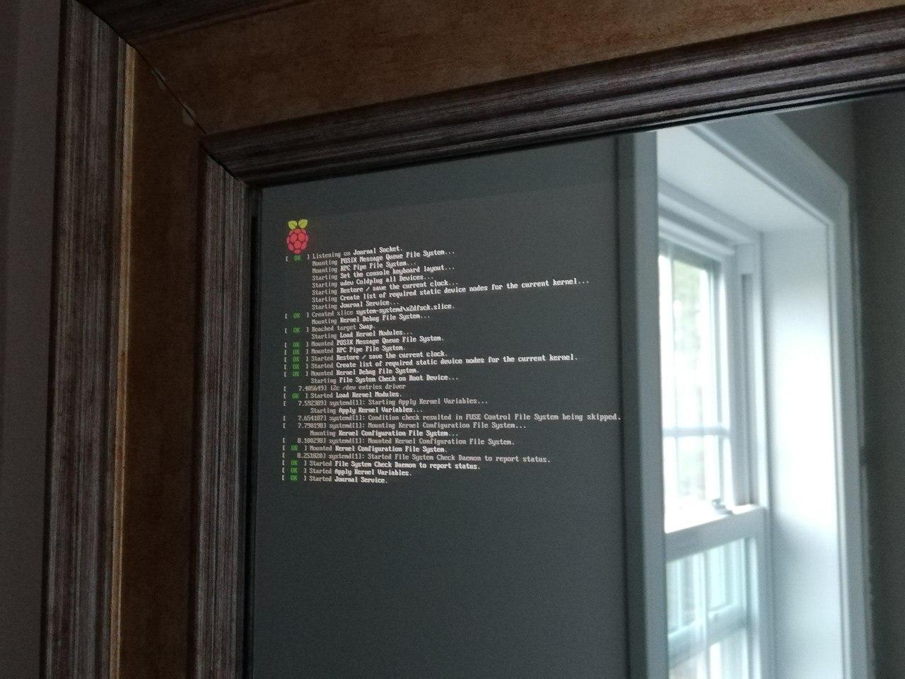
Success! Raspberry Pi is booting, and I am able to enable and disable the screen programmatically.
This motivation comes from years before “cutting the cord” was cool. For years I have wanted to get rid of cable, I am just tired of the excess fees that the cable companies charge, and how the rate just goes up month after month. Don’t get me wrong, they do deliver a good product, but to me it is not worth the price, and I don’t appreciate how they have no qualms with just raising the prices month over month.
Free TV
As you are probably aware, depending on where you live there are many great TV channels that you can receive over the air. For me, most of what I watch is prime time TV on the major channels, so this matches pretty well. You can search online at www.antennaweb.org for what would be available to you. For me, in the Boston area, this includes ABC, NBC, CBS, PBS, FOX, WB, and much more other minor content.
Tivo
While I am not a huge fan of cable, I have really come to love Tivo over the years. They have treated us really well over the last 15 years with our various Tivo devices, and have a great interface that works well. For cutting the cord, I ordered a new Tivo Bolt, which handles both Cable and also TV over the air.
Antenna
I had originally had a smaller powered GE antenna, but given that I am over 20 miles away from most stations and it didn’t consistently pull in all the major stations, I decided I must go with something more powerful. After doing some research, I ended up with the GE Pro Attic Mount TV Antenna. It ended up coming in a fairly small unassuming box, but after assembling and installing it, it performed beautifully.
Antenna installed in Attic on beam
Antenna installed indoors in attic pointing towards the majority of stations
Cord Cut
The finished product is working great. My antenna gets great reception, and when paired with the Tivo DVR provides a great service for those channels. In addition to that, Netflix and Amazon are a great compliment providing everything I could need.
It finally came to that point, where you have tons of cables sitting around and the mess comes to a breaking point. My home network is fairly complicated including a rack with various components, but for this article we will concentrate on the connections that interconnect in the Attic.
I have one main Ethernet line that goes from the switch in the basement to the attic, and from there it feeds a couple bedrooms and a couple Cisco Access Points using PoE. This setup was initially done over a little bit of time, adding one room after another, and one Access Point after another, which lead to wires scattered throughout the attic. My goal here was to fix all the clutter and clean that up.
My game plane was the following:
Reroute all the random lines, and put them in the wall thus removing the clutter.
Terminate all the existing lines on a patch panel (Cable Matters 12-Port), along with the main line from the basement.
Install a network switch with PoE support (TP-Link 8 Port PoE Switch), and clean up wire connections.
Well, it is all done, so here are some pictures of the rerouted lines, and the new patch panel/switch installed.
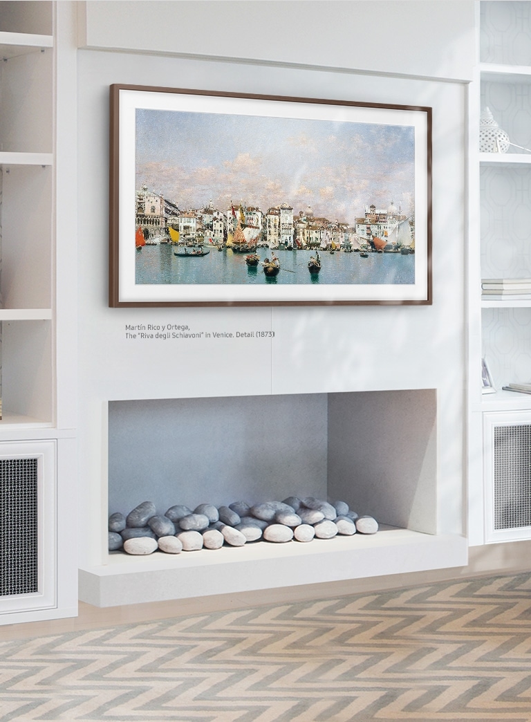
I have recently installed a Samsung Frame TV in our family room (story for another post…). It looks beautiful, works great, and when “off” does a beautiful job of displaying photos as almost art, I really encourage it for everyone to check out. My favorite feature is that when it is in the off-mode of the TV, it can show you any Art you would like, including custom uploaded content. This process for uploading images is manual though, and is fairly clunky. My dream would be for it to be automated, to show some of our great family pictures, and also maybe work as a smart home center, and display other useful information such as today’s weather.
I have always wanted a digital frame which I can fully control, which is part of the reason I bought this TV, and now maybe it can come to full fruition.
Project Goal: Show custom content on the TV when it is off in it’s art mode.
Background
The Frame TV works with a SmartThings Android App that allows you to connect to your TV and control basic functionality similar to a remote. In addition to this basic functionality, it allows you to upload custom Art and put a simple digital Mat around the image. This Art then appears every time the TV is turned off, and is shown for ambience. Below is what it the TV looks like in art mode:
Samsung Frame TV displaying Art.
Discovery Phase
SmartThings API
The SmartThings API is “the” Api from Samsung right now, so it seemed like the best place to start my investigation. I know that through previous investigations in this area that it allows you to control things such as turning the TV on and off. This Api lives in the cloud, and everything is controlled directly from there. While I have found that simple TV operations could be done though that interface such as controlling the TV input, I did not find anything related to the “frame functionally”, such as displaying images or being able to control displaying. Even TV state such as on/off does not seem to support the additional knowledge about being in an intermediate state where it is not On, and not technically Off (displaying black screen), but instead showing the Art work. When using the this is a concept, but it does not seem to translate to the Api.
Given all that, let’s investigate my next step. Since the Android app is able to do this, I attempted to reverse engineer the application. I followed instructions online of intercepting android traffic, and tried debugging the mobile app. In doing this it became clear that while the SmartThings API works in the cloud, the mobile application only allowed this “Smart TV” functionality when it was running on the same local network as the TV, and the authentication mechanism was different than that of SmartThings. This and other investigation led me to the idea that the app may be using Simple Service Discovery Protocol along with local API’s for this functionality, and not the SmartThings Api.
Simple Service Discovery Protocol (SSDP)
Through some local investigation I discovered that the Frame TV does support SSDP, and it provides multiple services through that, including discovering the TV in the first place. Through a little bit of probing, below are some of the services I discovered.
DIAL – Simple API for launching applications on the TV.
DigitalMediaDevice Interface – Generic Api for playing media.
While DIAL seemed to originally be promising, it only supports launching supported applications (eg. Netflix), and does not support generic content. Further investigation on the DigitalMedialDevice interface showed a AVTransport service which allows playing and controlling arbitrary streaming media. This may be starting to get interesting…
Digital Media Device
I found that the Frame TV supports a Digital Media Device interface which has a AVTransport device that allows you to control media on the TV. This allows you to discover, launch, play and stop content on TV. This supports showing stream content such as a movie, but also supports static content such as a particular image (eg. png/jpg). After some simple testing, and a decent amount of debugging, I was able to send a static image to the TV with the right HTTP/XML content.
Bingo!
While I do not know how to replace the current Art image, I have figured out how to show custom content to the TV. For now, this solution may have to do.
Solution
Now that we have a way to dynamically discover the TV device, and a way to show an image on TV, let’s put it all together into a potential solution.
Below is a high level of that solution:
Image Creation
So, the first challenge is generating content (an image) to show. After weighing the options, I decided that HTML was probably the best mechanism to describe content, and also very to create/debug using any browser. As a first step, I then created a simple html page. From there, I found webkit which is able to load website content, and generate an image from that.
While this would work fine on a system that supports X11 display, my server has no display to use. After a little research, I decided to try Xvfb. Xvbf is a virtual X11 framebuffer, which allows to paint and display items in X11 without having an actual real X11 display.
Below is an outline of the image generation:
Create HTML page showing content to be displayed on TV. This can include almost anything. For me, this is an image, the local weather, and some other various information.
Creating a python script that loads the html page in webkit (leveraging Xvbf), and then converts that to a static image.
Wrap this script as a web app, which returns an image as its output.
SSDP
As mentioned, SSDP can first be leveraged to recognize and discover the device. SSDP works by sending a UDP broadcast packed to the network, and then listening for all SSDP capable devices to respond. This will help us discover the device which we are looking to target, along with the interface that we are planning on using. Some simple python code can accomplish this.
SmartThings
While SSDP/AVTransport can be used to display an image, it unfortunately only works when the TV is turned on. This is where SmartThings comes in, SmartThings can be used to turn the TV on remotely, after which point SSDP can be used. Again, after some SmartThings registration are completed, this control can be accomplished from a little bit of python code calling the right interfaces.
Controller
The last piece, is to put together a controller which coordinates the other components, and runs as needed.
Final Solution
Now, let’s look at all the pieces together (reference diagram above).
Controller
Responsible for launching image on screen and clearing when necessary.
Calls SmartThings library for turning the TV on and off, calls SSDP for discovering TV and interface, calls TV interface for displaying content.
SSDP Library
Python library for discovering SSDP devices on the network, and returning their identifiers.
SmartThings
Python wrapper library for calling SmartThings API for a handful of commands.
AVTransport
Python library for calling TV interface XML API to start/stop media.
HTML Content
HTML webpage displaying content to displayed on TV. This is already optimized to look correct for 1920×1080 display (the best possible resolution on the TV).
Image Creation
Python CGI application for generating an Image. This is triggered by just hitting the application. Internally this follows all the steps outlined above to create the right image.
In its first release, the way that this works is that I have a cron job that launches every morning, which launches the controlled to display the content on the TV at a specific time. This is seen for a while, and then 45 minutes later the controller is launched again to clear the image and shut off the TV. This could use many refinements, but is good enough for what I needed in its first version. Below is what this looks like on a typical morning:
Conclusion
While this doesn’t accomplish exactly what I wanted it to do in the manner I was expecting, it does accomplish the overall goals of the original project. I am able to automatically display content on my TV, which updates every day, with almost no interaction from myself.
There was a lot learned during this project about the Samsung TV, different protocols that I wasn’t aware of (ie. SSDP, Digital Media Device standards, etc), and other technologies that existed. While it did not go nearly as smoothly as I had hoped, and took a lot longer than I expected, I am very happy with the results and am excited about how I can extend it further.
I hope that you find this informative, and if you have any of the missing gaps of information, then please share them.
Work recently offered to pay up to $50 to help decorate our cubicles recently. Question: How can I take advantage of this in the most ridiculous way?
“Light Bulb Goes Off”…
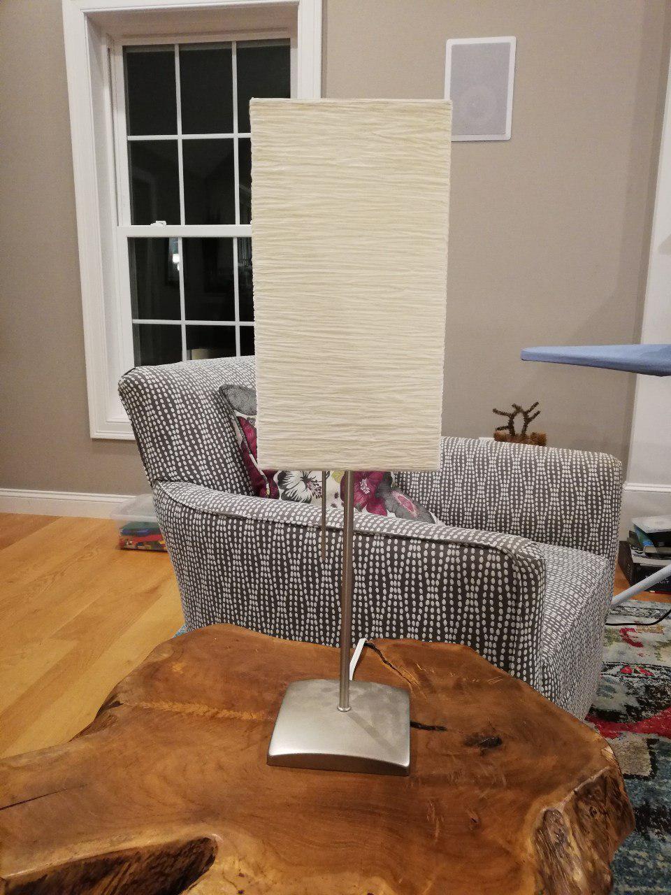
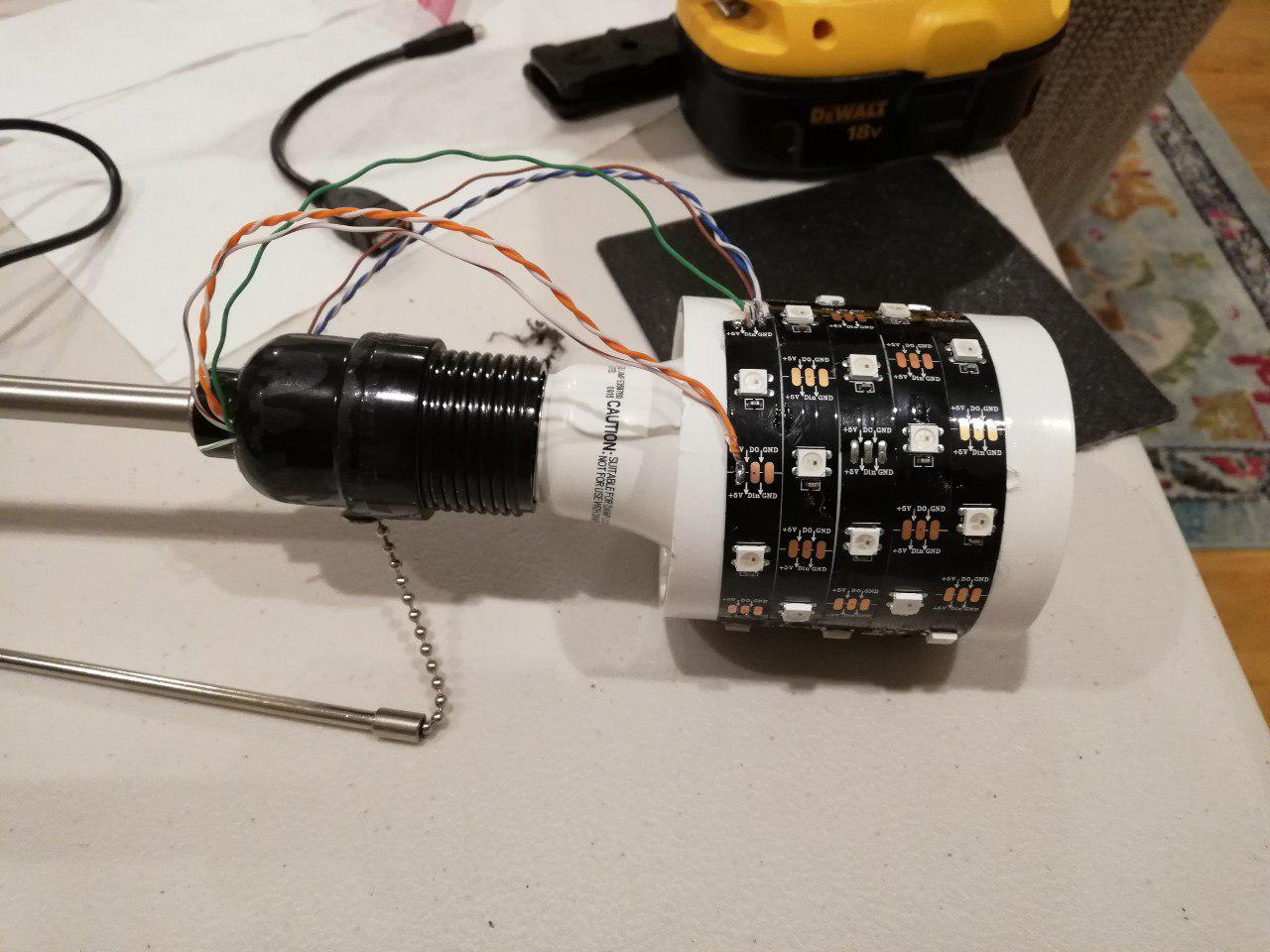
Create a intelligent desk lamp that can be aesthetically nice looking and notification mechanism at the same time. Old Ikea Lamp + Rasperry Pi Zero W + RGB Led’s => SSH capable Desk Lamp with 30 RGB Led’s.
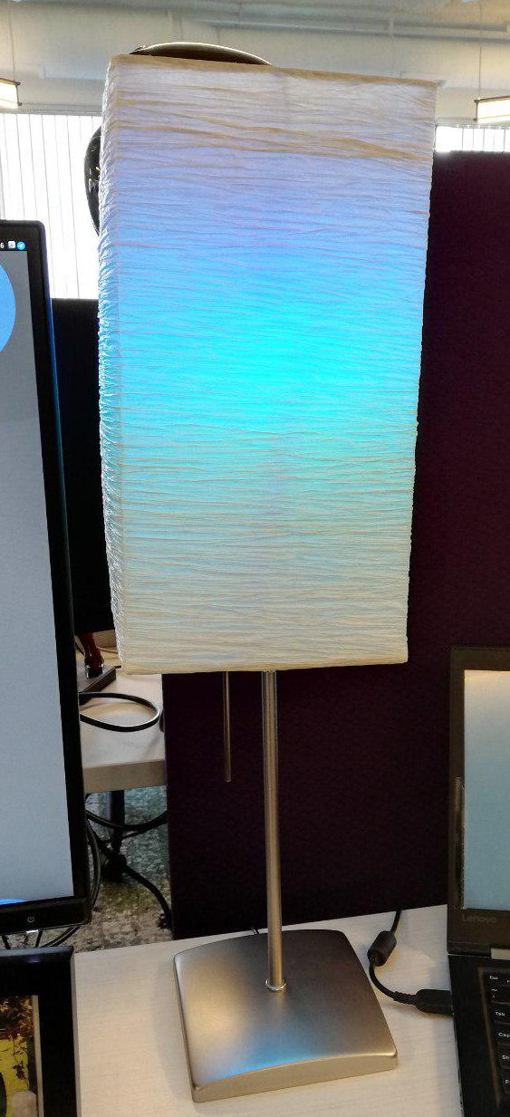
Final Product
Raspberry Pi Linux based Desktop Lamp running at 1 Ghz with 512 MB Ram on WiFi. 30 RGB Led’s controlled by python program, with pull-chain switch.
Build
Components
Old Desk Lamp
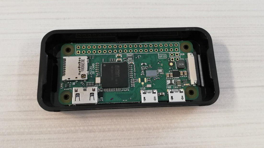
Raspberry Pie Zero W/SD Card (16GB)/Case
Micro USB Power Supply (2.5A/12.5W)
30 Addressable RGB Led’s (WS2812B)
Spare Ethernet Wire
10k Resistor
PVC Connector (for supporting LED strip)
Pictures
The original Ikea Lamp.
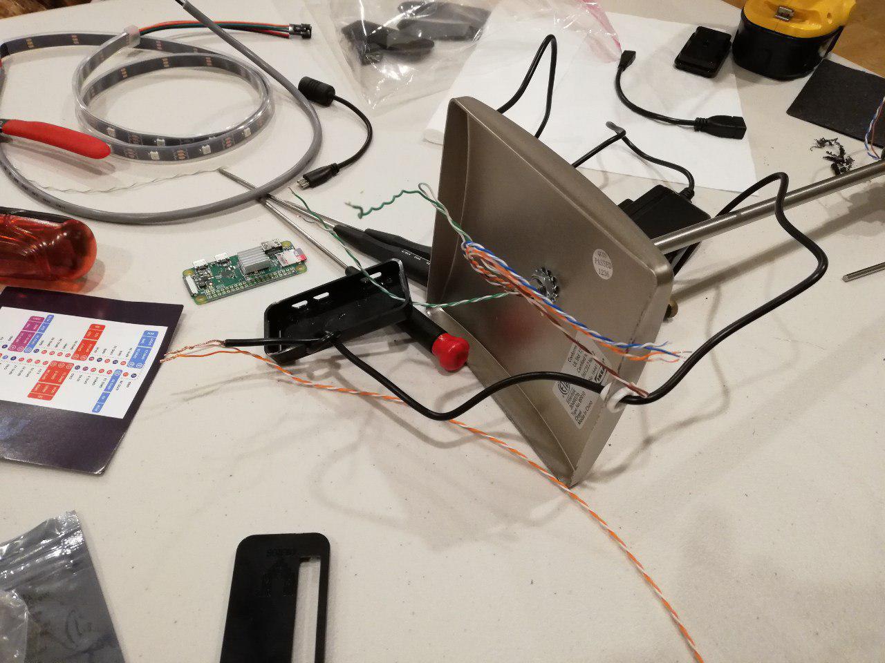
Raspberry Pi Zero W which will control the lamp.
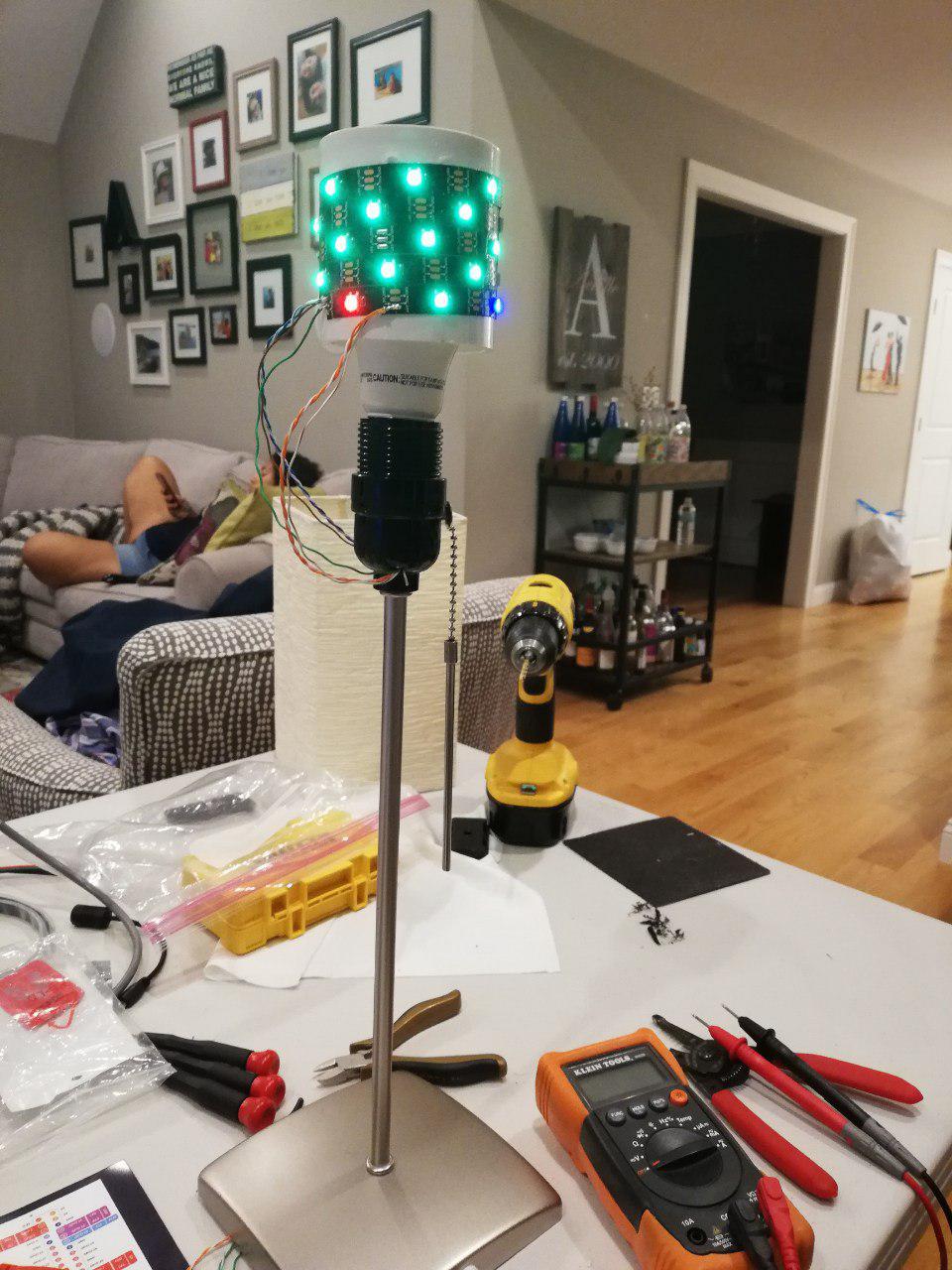
New LED light strip installed around original bulb.
Ethernet wires were repurposed through original lamp stem for signal and power.
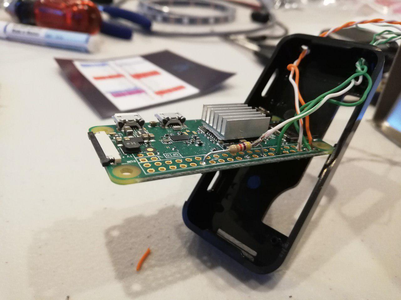
Wiring of Raspberry Pi for LED signal and switch sensing.
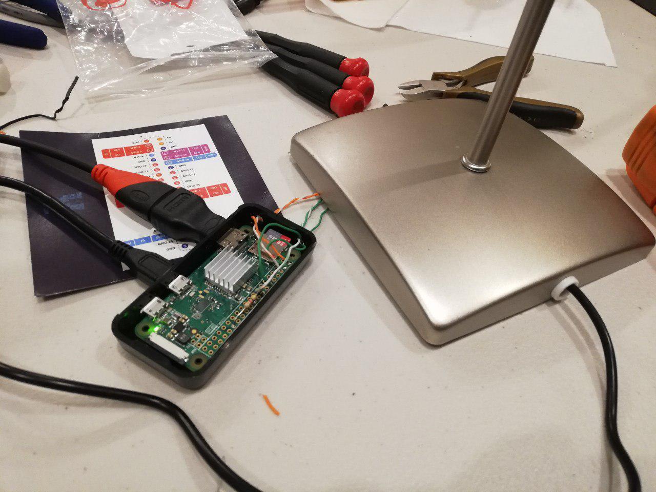
Installing and testing of OS.
First test to control LED’s.
Finished Product.
Steps
Disassemble lamp as much as possible. This includes disassembling light assembly and getting access to wires running up the stem, and removing those wires.
Drill holes in light assembly, and run new wires from base, through stem, and out new holes in light assembly. If possible also leverage existing switch and run wires to it. My setup contained the following:
3 wires in parallel for the LED strip. (+5V power. Used 3 to support current of LED strip.)
3 wires in parallel for Ground to the LED strip.
1 wire to LED strip for data to control strip.
2 wires to lamp switch as input.
Glue LED strip around PVC connector, and let dry. Solder wires to LED strip. Place PVC collar around existing bulb, and glue in place if necessary.
Take wires from stem and run into Raspberry Pi case. Power (+5V) should be connected directly to power supply, with one additional line going to Raspberry Pi. Ground (GND) should be connected directly to power supply, with one additional line going to Raspberry Pi. LED data line should be connected directly to Raspberry Pi, and Switch lines should also be connected to GND and +5V with a 10k Resistor.
One interesting insight that I learned, is that the Raspberry Pi Zero W does not need to be connected to power via the Micro USB port. Since the Raspberry Pi does not have a voltage regulator for the 5V, you can back feed the power directly via the GPIO +5V/GND lines.
Make sure wires are in their final location, before soldering them all together. (ie. make sure power line is routed where you finally want it)
Power the Raspberry Pi, and connect to monitor and keyboard. If you have not installed the OS, then do it now, and make sure you have a way to connect to it remotely (ie. enabling SSH). Also run some sample program to test the LED lights are working correctly.
If necessary, debug hardware and/or software problems.
Place Raspberry Pi in the base, and attach as necessary. If possible, put base cover back on lamp and finish assembling back together.
Place on desk, and enjoy. SSH and update as necessary.